Understanding Critical Parameters In Resistor Selection – Ohms Law
Going back to college fundamental physics is helpful in understanding the most commonly used parameters used in specifying wirewound and power resistors. Good engineering practice will generally mean that a certain degree of ‘over specifying’ will result in long term reliability and performance of the final product – be it a motor control circuit, power supply, resistor bank, heating or cooling appliances or printed circuit board control circuitry.
Resistance – Ohms Law
Ohms law is possibly the most fundamental equation taught in electrical engineering. It is the foundation principle used to determine the relationship between 3 basic components of electrical theory, namely:
- Voltage
- Current
- Resistance
Stated in simple terms, ohms law dictates that electrical resistance is calculated by dividing the applied voltage to the resistor by the current flowing through that resistor. As an equation we define
Resistance (R) = Voltage (V) / Current (I) or R=V/I
By using simple algebra we can rearrange this formula in order to determine the voltage across a resistor and the current flowing through the resistor. This is represented in the following equations:
Voltage (V) = Resistance (R) x Current (I) or V=IxR – the voltage ‘dropped’ across a resistor is equal to the resistance value (measured in ‘ohms’) of the resistor multiplied by the current (measured in amps) flowing through that resistor.
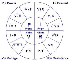
Current (I) = Voltage (V) / Resistance (R) or I=V/R – the current flowing through the resistor is equal to the voltage applied to the resistor (measured in ‘volts’) divided by the resistance of the resistor (measured in ‘ohms’). The graphic below shows the algebraic ways in which power, current, voltage and resistance can be related to each other:

Ohms Law
Power Ratings Of Wirewound and Power Resistors and Ohms Law
So far we have seen how ohms law, using parameters of voltage, current and resistance can be manipulated by simple mathematics to determine, for example, what voltage we can expect to see across a resistor when we know the voltage flowing through the resistor and the value of that resistor. However, it is crucially important when selecting the correct power resistor that we ensure that a suitable ‘wattage’ is selected. Wattage is a measure of electrical power. Again ohms law comes to the rescue when we need to determine the power ‘dissipated’ in a resistor. By ensuring the resistor we select for our application has a sufficiently high power rating, we ensure the resistor will operate with maximum reliability in our circuit.
Ohms law specifies that the power dissipated in a resistor is equal to the voltage dropped across that resistor multiplied by the current flowing through the resistor or:
P (power, measured in ‘watts’) =V (Voltage, measured in ‘volts’) x I (Current measured in ‘amps’)
or P = V x I
Again, we can use some simple algebraic manipulation to express power (P) in terms of resistance (R) and current (I) only. In this case:
P (power, measured in ‘watts’) = I (Current measured in ‘amps’)squared x R (Resistance measured in ‘ohms’)
or P = I² x R
Wirewound Resistor Power Rating Examples
Ok, so now we have an understanding of how the electrical parameters of voltage, current and resistance work together and allow us to calculate power ratings in an electrical circuit, we can look at how we can determine the appropriate wattage of a power resistor for our particular application.
Example 1. Lets say we have an application where we have a d.c. circuit operating with a 24 volt d.c. power supply. We want to drive a 12 volt d.c. motor that draws a current of 5 amps. We therefore need to select a power resistor that will allow us to ‘drop’ 12 volts across it and have the 5 amp circuit current flow through that resistor. We can use ohms law in 2 ways now to determine the required resistance of the resistor and the required power rating of the resistor:
Required resistance. From the above discussion we know that:
Resistance (R) = Voltage (V) / Current (I) or R=V/I so for our example we have:
Resistance (R) = 12 volts / 5 amps = 2.4 ohms
Ok, so what is the required power rating of the resistor?
In this case from the above discussion we know that:
P (power, measured in ‘watts’) = I (Current measured in ‘amps’)squared x R (Resistance measured in ‘ohms’)
or P = I² x R so for this application we have:
Power dissipated in the resistor and power rating required = (5 amps) ² x 2.4 ohms = 25 x 2.4 = 60 watts
Alternatively, we could have calculated the the required power rating of the resistor using the formula P = V x I. In this example it would be:
Power dissipated in the resistor and power rating required = 12 volts x 5 amps = 60 watts
Ok, so now we know, that for this application example we require the following power resistor:
2.4 ohms 60 watts. We can select the appropriate power resistor from our range taking into account our physical size constraints (or not), the way in which we need to mount the resistor into the finished product ( eg, p.c.b. mount, low profile mounting etc etc).
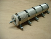
Some solutions for this example could be the ES tubular power resistor which has a rating of 75 watts. We choose this as the next lower available power rating is the ‘EP’ resistor which only has a 50 watt rating. By using the ES 75 watt rated power resistor we ensure we have some ‘leeway’ over the required 60 watt rating – which makes for good engineering practice as discussed in the introduction of the article.
Other Options For A 60 watt Resistor. As well as the ES 75 watt resistor, we could also use the low profile FRW series flat wire wound power resistor which is perfect where space constraints make a lower height power resistor a requirement. A 65 watt or 75 watt option would be available for this application from the FRW series. Again, it could make sense to use the higher 75 watt option.
Yet another option can be found in the metal clad resistor range – where the GMR series is available in an 80 watt version. The metal clad power resistors (often referred to as ‘aluminium housed’ resistors) have the benefits of small size for their power ratings and easy mounting.
Conclusion
So we have seen that ohms law can be easily applied to basic electrical circuitry to determine electrical resistance, current flow, applied voltage and power ratings. This ‘cornerstone’ formula is extremely helpful in correct resistor selection for your application and circuit.

